Why Grangemouth to Granton?
The Grangemouth to Granton pipeline was chosen as it is representative of LTS pipelines across Great Britain in terms of age, grade of steel, and key features along the route, such as road, river, rail crossings and parallel pipelines. Consideration of these features is critical for the safe operations and emergency response to pipeline incidents. The pipeline isn’t connected to any consumers, such as businesses or homes, meaning the trial could be completed with no impact to customers.
Preparations for repurposing
Prior to the Live Trial, several above-ground surveys of the pipeline were completed. This included full line-walks, coating and cathodic protection checks. Several small digs were completed for further visual inspection. The pipeline was then internally cleaned and inspected using a gauge ‘pig’.

Figure 4: Gauge Pig
Watch a gauge pig being inserted into the pipeline.
After cleaning and inspecting, a hydrotest at 1.5x the maximum operating pressure was completed successfully. This standard pipeline test involves pressurising the pipeline with water to ensure integrity prior to introducing gas.

Figure 5: Setup for pigging and hydrotest
These in-situ tests and surveys fed into a design and operability assessment, concluding the suitability of the pipeline for the Live Trial. A comprehensive integrity management plan was also developed and followed in the lead-up to the Live Trial.
Our Case for Safety and Operating Procedures
In preparation for the live trial, a Case for Safety was developed. This, along with our procedures, detailed how we would carry out operations during the trial and ensure everyone’s safety – a priority for us. The Case for Safety was reviewed by the HSE prior to the trial, following the same processes as the existing natural gas network. Our Safe Control of Operations (SCO) process was used during the trial to ensure that the same standards of safety expected of our natural gas network were used during the trial.
Emergency response simulation
Emergency services, including SGN, are the first responders in the event of any crisis. We work together with local authorities to make sure we have plans to deal with these incidents safely. Before the live trial, we carried out an exercise with representatives from emergency services, local authorities and the HSE to understand how a multiagency response would react to a simulated a hydrogen emergency. This allowed participants to understand where existing plans needed to be adapted for hydrogen.

Figure 6: Emergency response simulation exercise
Live Trial Construction
To connect our Grangemouth to Granton pipeline to a hydrogen supply, we constructed a new 1.5 km high pressure hydrogen pipeline. This was the first pipeline to be designed and constructed in accordance with the UK hydrogen pipeline design code and provided a link to our hydrogen supply project partner INEOS.

Figure 8: Welding on the 3" hydrogen supply pipeline in partnership with AGL

Figure 9: Excavation for the installation of the hydrogen supply pipeline at Bo'ness Road in partnership with AGL
Throughout 2024, we constructed and repurposed above ground installations (AGIs) along our pipeline to support our Live Trial operations. AGIs are commonplace on the LTS, incorporating control systems and monitoring instrumentation for our pipelines.
Our Live Trial AGIs provided live data to the operations and project team, allowing us to control and monitor several parameters during the Live Trial including pressure, temperature and flow. As the pipeline was used for a short duration trial and not connected to any offtakes, an enclosed ground flare (EGF) was erected at the termination point. This allowed us to safely combust the hydrogen in the pipeline when flowing gas operations were required.
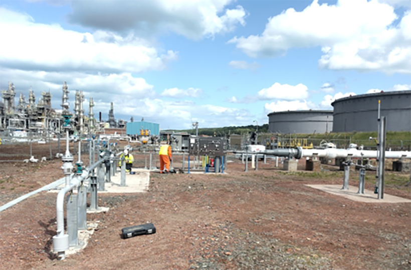
Figure 10: Kinneil Entry Unit and connection to the Grangemouth to Granton Pipeline

Figure 11: Safety shut off valve at Kinneil Entry Unit
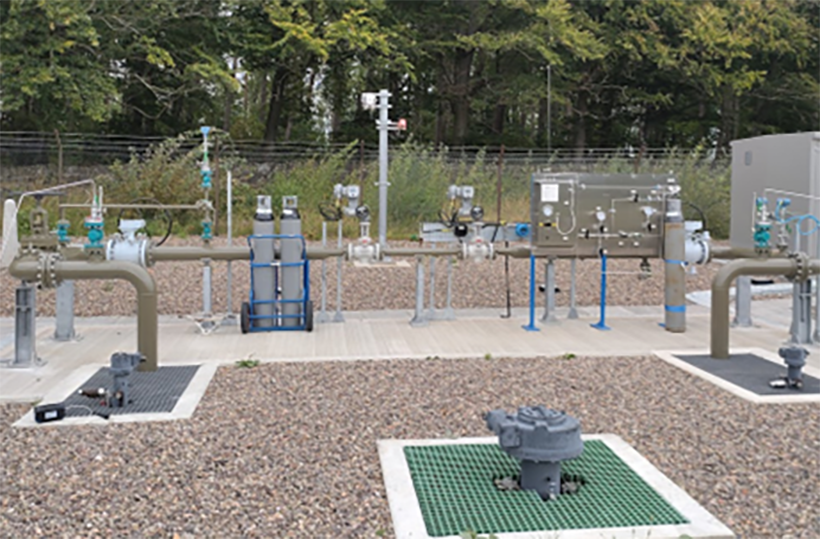
Figure 12: Newton Block Valve By-pass

Figure 13: Bo'ness Road Compound
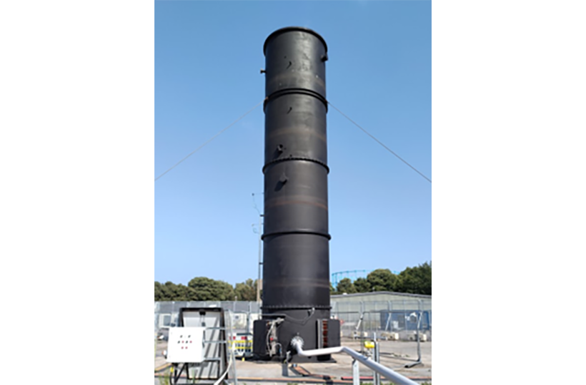
Figure 14: Enclosed Flare at Granton provided by project partner Zeeco